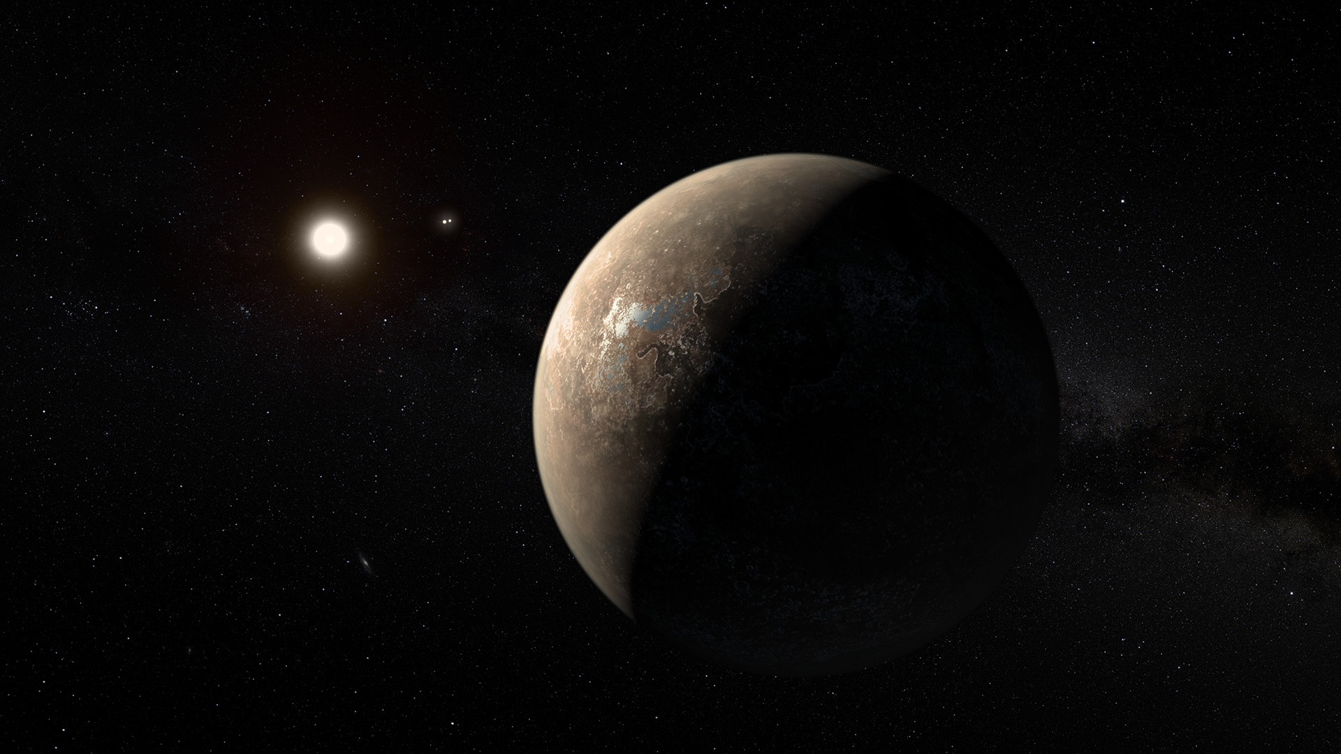
As mysterious as the worlds of our own solar system are, the worlds of other star systems are not only far more mysterious but also far more numerous. We know little about them other than their mass, size, and distance from their star. The details about what, if anything, dwells on their surfaces and within their oceans and atmospheres are largely obscured by the blinding intensity of their neighboring star. At the immense distances of these exoplanets, the angular distance between the star and its planets is so minuscule in the night sky that it would be like trying to see a moth flying around a bright light in New York from California. Although space telescopes allow us to see farther than ever before, the brightness of a star greatly limits what we can learn about the worlds that surround it.
As of February 1st, 2023, there are 5304 confirmed exoplanets in 3,910 star systems, with 853 systems having more than one planet.
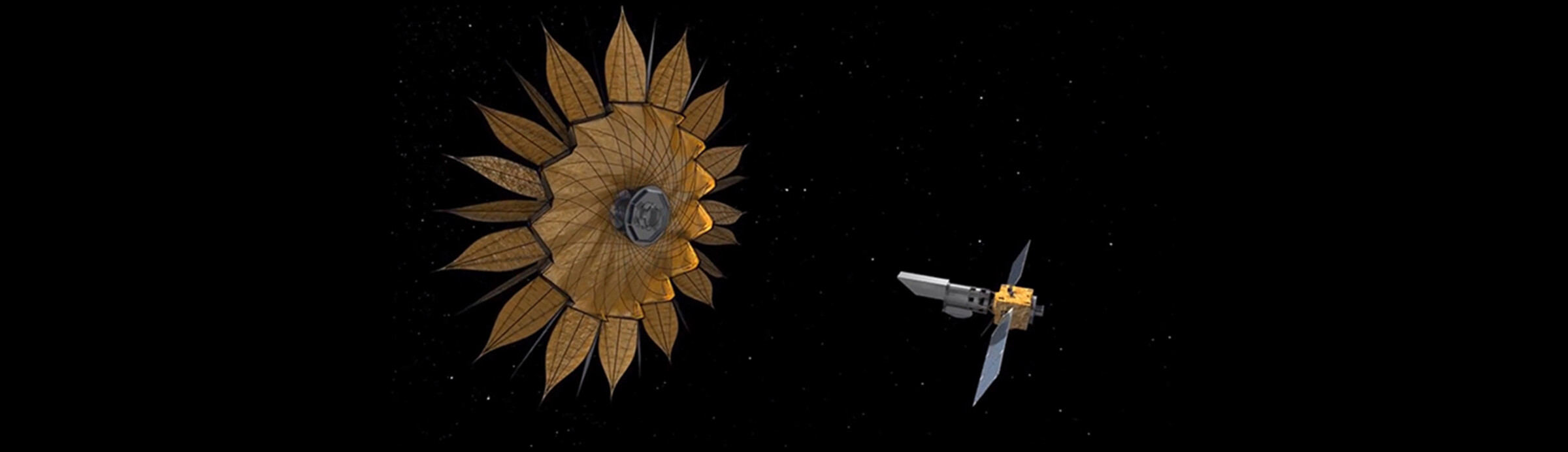
The starshade concept was first advanced by Webster Cash at the University of Colorado Boulder through the NASA Institute for Advanced Concepts (NIAC) program. This large occulter would later become known as the Starshade, and its design would be resumed at NASA’s Jet Propulsion Laboratory. By directly imaging exoplanets in far greater numbers than ever before possible, scientists could study the chemical compositions of a great diversity of otherworldly atmospheres. Within those atmospheres, the presence of water, methane, CFCs, and a wealth of other chemical compounds could be detected through their emission spectra and monitored over time. The analysis of these chemical signals would allow for the detection of habitability and even extraterrestrial life.
Video pending restoration.
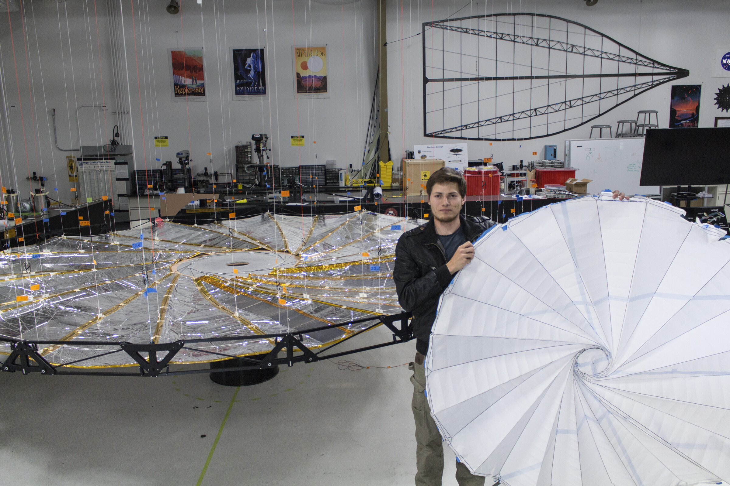
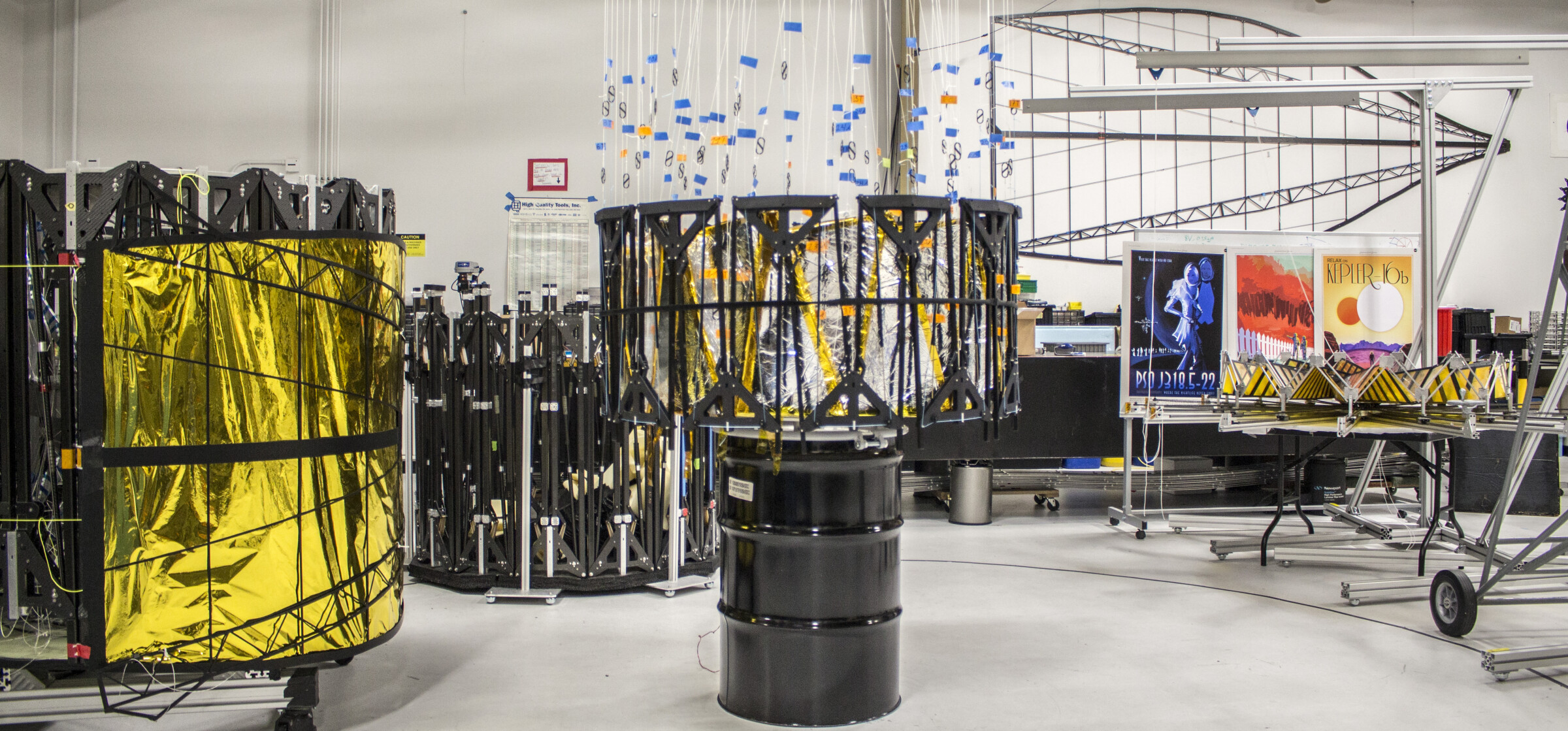
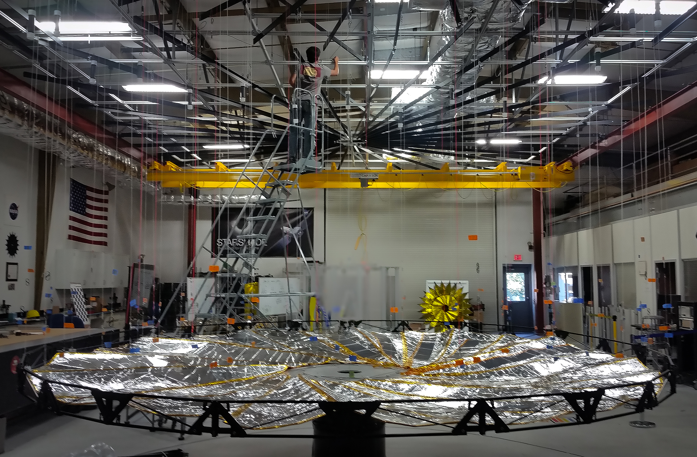
To prevent any starlight from reaching the space telescope located approximately 4 Earth diameters away, the Starshade would have to take on a special sunflower-shaped perimeter that prevents the diffraction of starlight around its edges and into the space telescope. Additionally, the Starshade would have to be very large to cover the star at such a great distance from the space telescope. The Starshade’s size and shape would require special modifications to fit into the rocket that delivers it to orbit around the Sun. Ultimately, these modifications would require the Starshade to deploy autonomously in space from a small, compact package with an origami-folded optical shield surrounding its core.
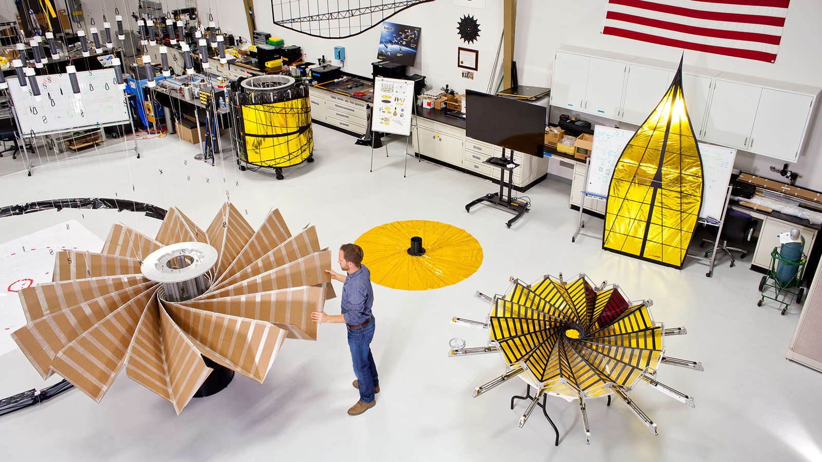
The Starshade is primarily composed of four concentric components: a central hub where the propulsion system is located, a starlight blocking optical shield, a deployable mechanical truss, and a periphery of starlight diffracting petals. It must fit into a cylinder a few meters in diameter, yet span 10-20m in diameter and deploy autonomously in space. In order to accomplish this, the Starshade team designed a deployable truss to carry the petals and optical shield to their deployed positions. While the petals had been designed such that they could curl around the stowed truss and stiffen once deployed, stowing and deploying the optical shield proved a complex problem.
It was later suggested that the ancient Japanese art of origami may be the solution to compactly collapsing such a large disc into such a small cylinder while respecting the other requirements. For an origami design to be successful it would need to satisfy seven requirements however.


Brian Trease from JPL and Shannon Zirbel from Brigham Young University led the initial attempts to overcome the origami challenges. They started by examining Robert Lang’s Eyeglass Telescope, a very thin origami deployable fresnel lens, and tweaked the parameters that defined its crease pattern. Their efforts yielded promising results.
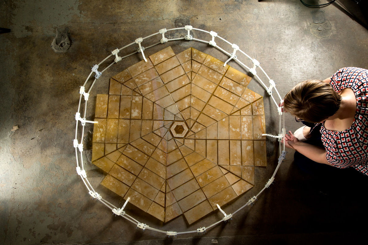
When viewed as a vector field, crease patterns can be concentrated using two primary methods: convergence and curl (or combinations thereof). Robert Lang’s Eyeglass Telescope design utilized curling, which offers the advantage of minimal crease complexity for a rigid, foldable origami. To accommodate the thickness of the panels during folding, Trease and Zirbel introduced gaps into their design. The origami could be deployed using a single degree of freedom, potentially provided by the truss deployment.
Although the crease pattern met several design requirements, including folding rigid panels into a compact cylinder, it faced challenges in maintaining a perfect light seal with the truss during deployment and folding from a conical disc. The crease pattern could meet the stowed outer diameter constraint or the inner diameter constraint, but not both simultaneously.
The equations behind Robert Lang’s Eyeglass Telescope crease pattern were designed for ultrathin materials, and adjusting them to accommodate the thickness of the optical shield resulted in nonuniform thickness accommodation. This caused the panels toward the center to get crushed and those toward the periphery to have gaps, leading to a stowed diameter too wide for the truss’ inner diameter and damage to the inner panels and hinges.
Similarly, the Eyeglass Telescope’s deployment mechanism differed from the Starshade’s, and the crease patterns generated by the equations did not allow for the origami deployment to match the truss kinematics. As a result, the current optical shield crease pattern could create a light seal with the truss, but would detach and create gaps during stowage and vice versa during deployment.
Moreover, the lack of research on origami folded from conical sheets meant that the team would need to develop the necessary mathematical tools to design crease patterns that could fold from cones.
These three remaining requirements posed persistent challenges for the Starshade team over the subsequent years.
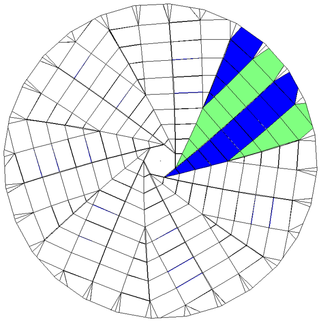
In the summer of 2015, I was invited by Brian Trease to join the team and utilize my expertise in origami design to tackle the remaining design challenges. During the briefing, it became clear that the light seal requirement couldn’t be met by the current crease pattern, while the thickness accommodation and conical crease pattern problem presented even greater difficulties.
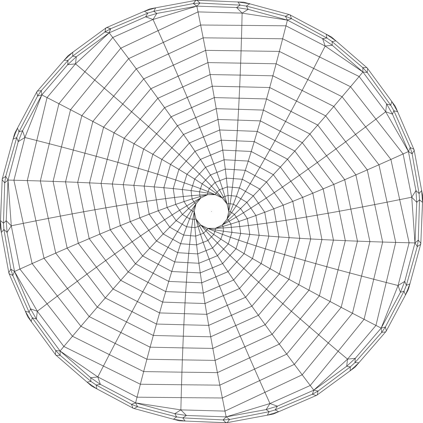
The design utilized folded features called rings to limit the stow height. These were curved V-shaped creases that pointed toward a ring of points around the center. While the rings helped to limit stow height up to a maximum, they discretely increased stow width for shorter stow heights. The current design stood at 7 pairs of gores with a set of two rings; (Maximum stow height) / (number of rings) = stow height. The caveat to using these ring folds was that the length of the crease that bisects the ring of V-shaped creases were longer than the V-shaped creases themselves, yet each spans the same distance, from the lower inner stow diameter to the lower outer stow diameter. Consequently, two sets of creases of different length along a disc that originate the same distance from stow center and terminate the same distance from stow center, cannot terminate the same distance from center when in the deployed state (since one set of creases is longer). In effect, the use of ring folds inevitably leads to a crease pattern that will match the inner perimeter of the truss in the stowed state, but will bunch up in the deployed state (because the V-bisecting creases are now too long) or a crease pattern that will match the inner perimeter of the truss in the deployed state, but will tear away from the truss during stow (because the V-shaped creases are too short). The team having been aware of this were prepared to reconcile this mismatch by appending the optical shield with stretchable materials to make up for the missing distance of V-shaped creases. The appendage of these stretchable materials, “soft goods”, would have the unintended consequence of creating slack because the truss and the hub during deployment however. A novel origami design would be required.
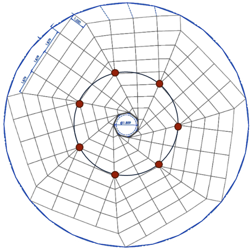
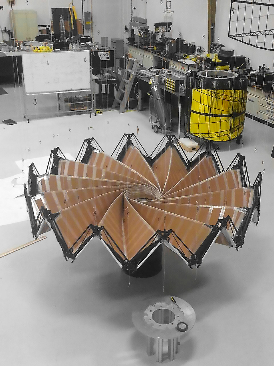
In order to prevent this truss detachment problem, I knew the creases that bisected the V-shaped creases had to terminate at the top outer edge of the stow cylinder, since it allowed the long bisector creases to travel father through the stowed geometry than the shorter V-shaped valley creases that terminated at the bottom. This would at least reduce the missing peripheral distance to the truss. Using Robert Lang’s Eyeglass Telescope equations, I got to work designing an alternative pattern, one with only a single ring, that allowed the longest creases to travel the farthest through the stow geometry. A shift to single ring, also meant the crease pattern would now need 14 pairs of gores instead of 7.
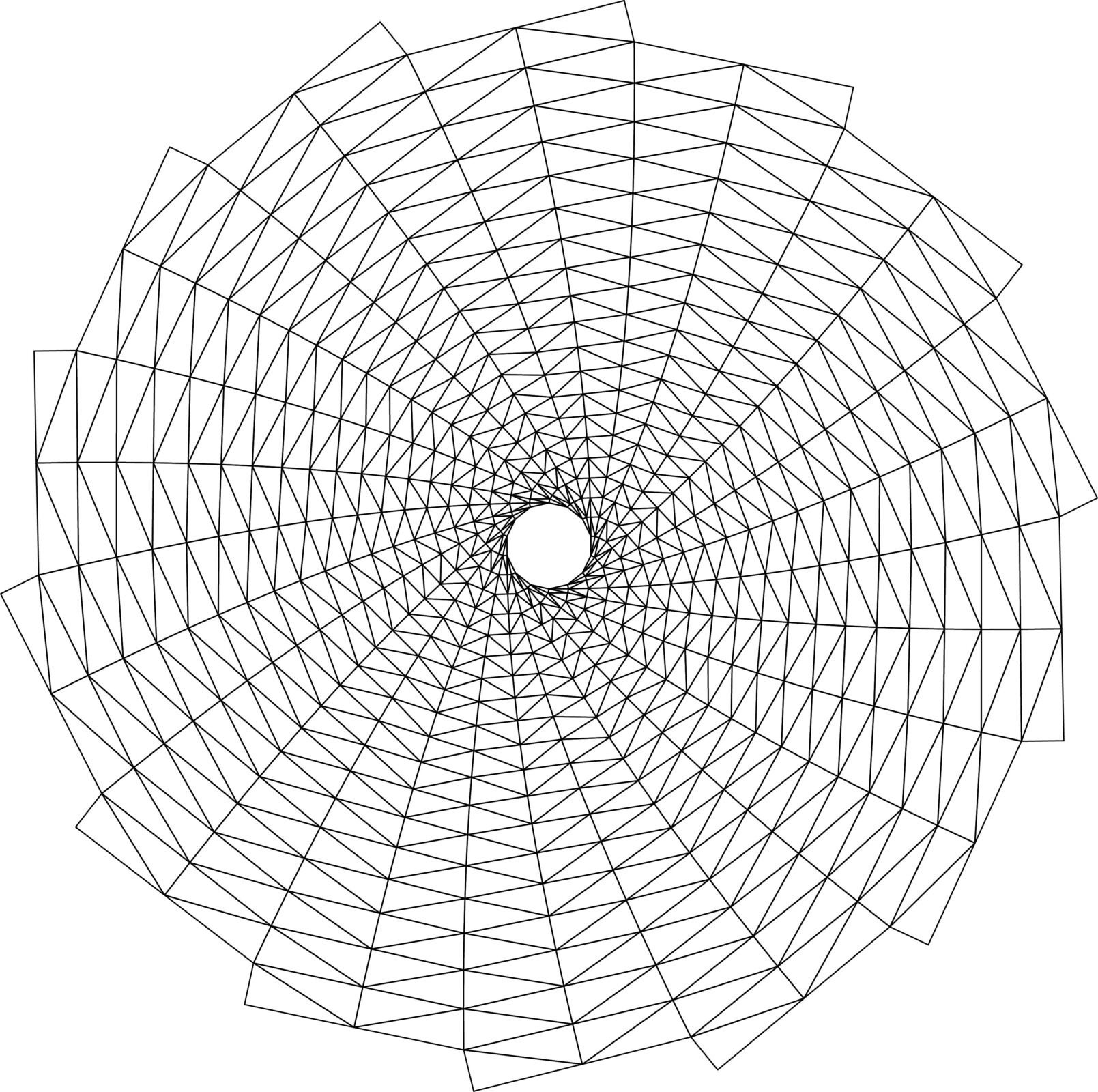
The missing peripheral distance during stow was indeed reduced, but remained. The trouble with thickness accommodation likewise remained, too little accommodation near the center, and too much near the periphery. Regardless, it was the first big advance in quite some time, and worthy of a prototype to assist in resolving the remaining challenges.
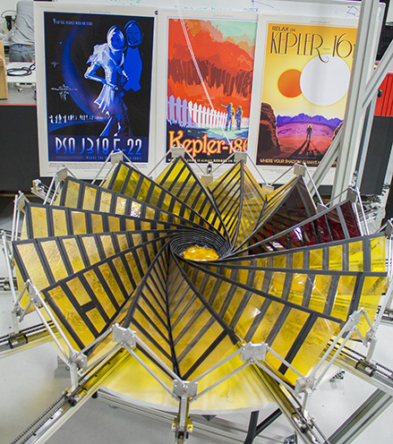
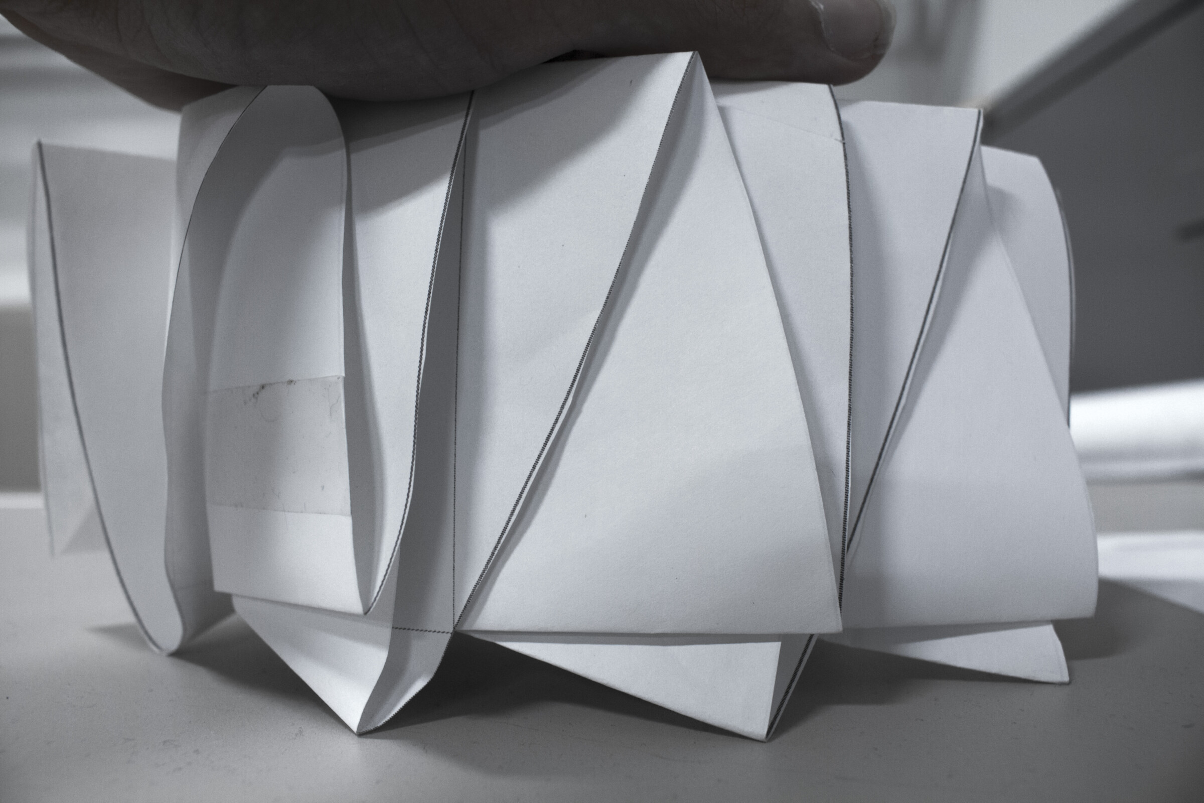
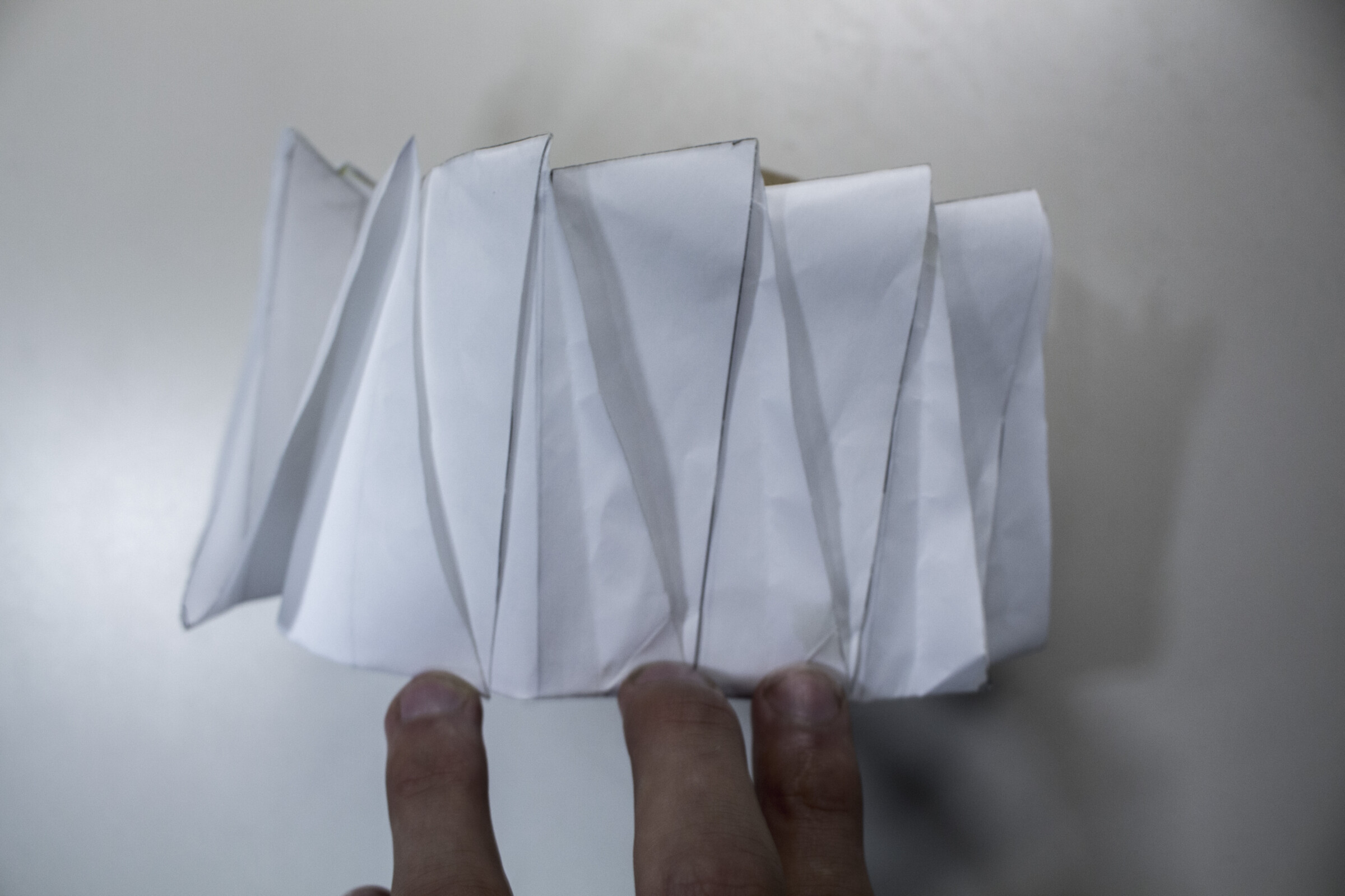
Earlier efforts to match the truss kinematics by modifying the 7-gore pair crease pattern at the periphery had proved futile. Reflecting on these attempts, I found that the problem lied in the angular frequency of the folded perimeter of the optical shield. Since the angular frequency of the 7-gore pair origami was twice that of the truss, ~143mHz to ~71.4mHz, a folding operation to match the two edge conditions could n0t be possible. Now, with a 14-gore pair crease pattern, the angular frequencies matched precisely, at ~71.4mHz. With the two frequencies now in harmony, it should then be possible to apply a folding operation, or transformation to the peripheral crease pattern to match the boundary conditions of the truss throughout deployment.
Now that the angular frequencies matched, the waveform would have to match as well, and that could be accomplished through a folding operation. The waveform of the truss was a Dirac comb with a frequency of 71.4mHz, and the waveform of the 14-gore pair crease pattern was an asymmetric triangular wave of the same frequency, but of greater amplitude. Although the amplitude of the 14-gore pair crease pattern was higher, the inner perimeter of the truss and the outer perimeter of the optical shield were equal, so any successful transformation of its asymmetric sawtooth to a Dirac comb would also yield a matching amplitude.
Foremost, I set out to transform the asymmetric triangular wave to a symmetric one, then finally to the Dirac comb. I folded an angle bisector crease between all the corners of the icosakaioctagon until they met the dominant mountain fold, at top, or the dominant valley fold, at bottom. From the intersection of the angle bisector to the dominant mountain fold, I folded a vertical crease down toward the dominant valley fold. From the intersection of the angle bisector and the dominant valley fold, I folded a crease to the previous intersection at the dominant mountain fold. These two folds brought the sides of the asymmetric triangular waves clockwise into a symmetric triangular waveform that protruded from the stow volume an arbitrary distance that was ultimately related to the degree of rotation between the icosakaioctagon perimeter and the interior of the crease pattern. From this triangular waveform, I sought to transform it to the Dirac comb and bring it back to the surface of the stow volume. I next brought the two sides of the triangular wave together, colinearly, and rotated them clockwise around the stow volume, before rotating them back counterclockwise radially parallel to the vertical crease I folded initially, simultaneously creating half a petal fold at the bottom. This amounted to the formation of a Dirac comb waveform that protruded from the stow volume. Very close now, I brought the two side of the colinear Dirac waves toward the center of the stow volume, colinear now with the vertical crease I folded initially, this created a petal fold at top and completed the petal fold at bottom. Finally, I folded a crease between all the Dirac waves at bottom that brought half the icosakaioctagon corners outward, completing the Dirac waveform on the surface of the stow volume. The boundary conditions of the crease pattern now matched that of an appropriately sized truss. A match that promised a perfect light seal throughout deployment.
Starshade had a nontrivial problem of how to make the geometry and kinematics of the expanding ring truss match the kinematics of the baseline deployable origami pattern. The two elements packaged very nicely together, but were incongruent at their mechanical interface, with each preferring its own complex 3D motion through space. Most of the team assumed no solution could exist and that we’d need to implement an elaboration of stretchable fabric and cables to complete the system. However, Robert eagerly took on the challenge. After a few days of nonstop work and many prototypes, he had an elegant folding solution that mated perfectly with our scaled truss hardware. The two moved together in harmony during their deployment, and instantly won over all the doubters.

Although this new periphery crease pattern matched the waveform of the truss, the origami was still too wide when stowed within the truss to remain confined. After having exhausted the design space spanned by Robert Lang’s Eye Glass Telescope parameters, I knew a new set of equations would be necessary to stow the optical shield tightly around the central hub while accommodating its large evenly distributed thickness.
Starting with the basics, I designed a crease pattern that accommodated no thickness at all, preluding to an attempt to fold it with thicker physical material and see how the true creases drifted from the crease pattern. A comparative analysis between the crease pattern and the true crease pattern was sure to offer insights in how accommodated thickness influenced the folds.
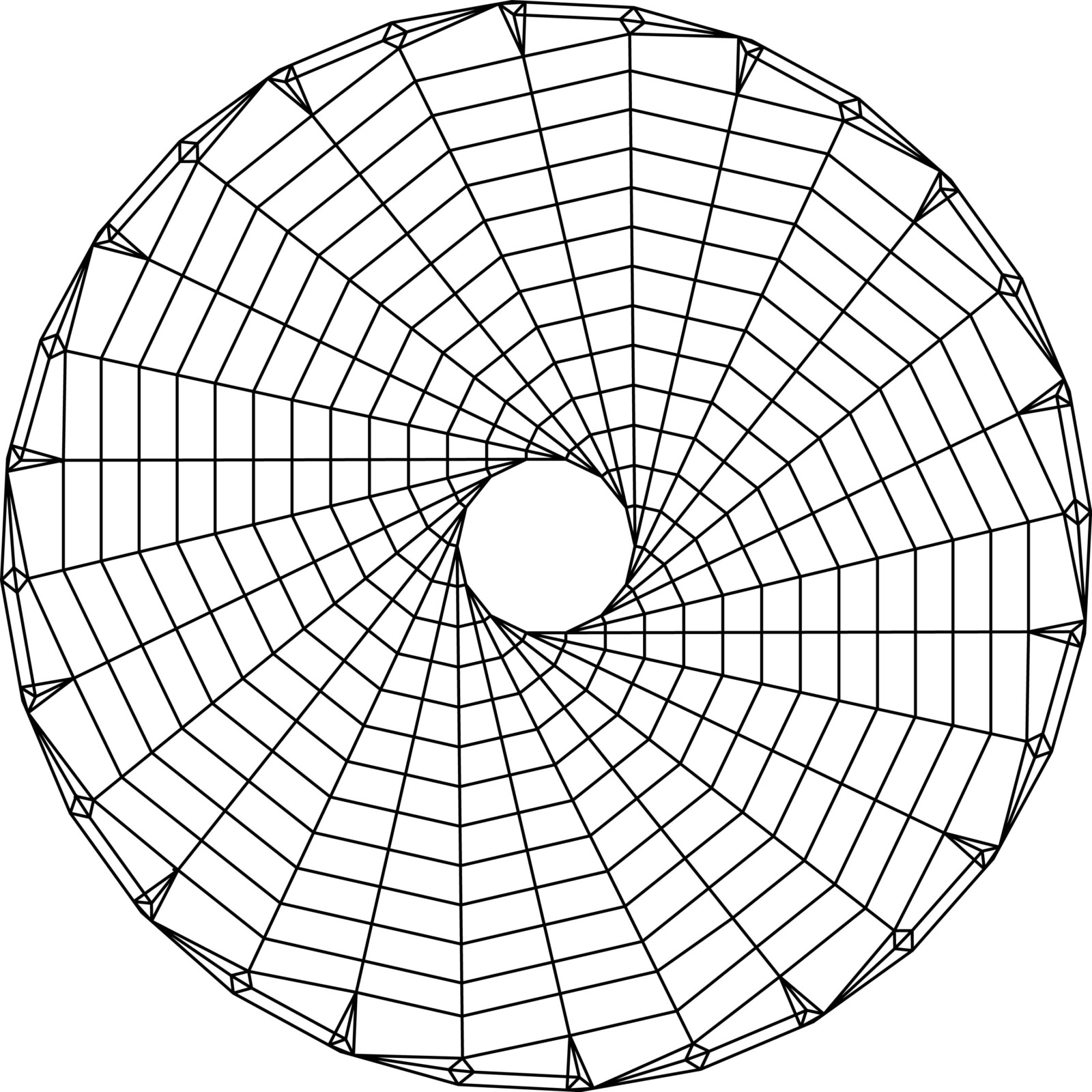
It was clear that folding crease patterns such as this, with thick materials and maximum compaction (no gaps between panels) resulted in curved folds emanating from the central disc. Higher curvature nearer the center, and lesser nearer the periphery. Subsequently, I decided to pursue a strategy of reverse engineering. First starting with the 3D folded form of the origami that we needed and working out the geometric relationships that would allow me to solve for the crease pattern that would fold such an origami. I started by drawing the desired bottom surface of the origami, the plane where the dominant valley folds resided. Advancing with trigonometric relationships, I worked out the necessary lengths of the segments (panel edges) that constituted the length of the dominant valley folds. I took these relationships, summarized them into an equation that would be valid for a large range in thicknesses (encompassing any thickness that would still produce viable origami) and generalized the relations to include spiral deploying origami with any number of gore pairs and any diameter of inner or outer disc. I now knew what length the valley creases should be, but the angles between these segments was still unresolved, and without them I could not produce a crease pattern. I only knew that when I did finally solve for these angles they would yield a chain of valley segments that would approximate the curves I had seen when freeform designing a solution. In order to garner more insights, I decided to produce a crease pattern with these valley segments anyway, choosing an interangle arbitrarily to see how the origami would behave when folded this way.
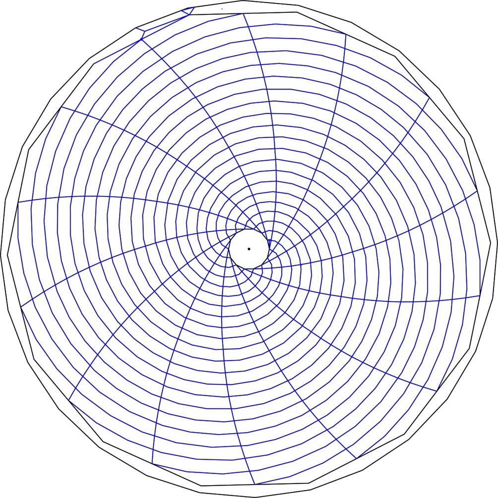
The results were interesting. The origami itself was quite wide and spacious, accommodating for variable thickness, as was to be expected from a dominant valley fold of such consistent curvature. There was a clear relationship between the angles between the valley segments, the thickness of material accommodated there, and the distance from center or anything else proportional to distance to center, such as the height of the origami at that point. Thusly, I wrote an equation that describes the 3D geometry of a mountain fold as it rises from a plane occupied by two intersecting valley folds coming together and decreasing the angle between them.
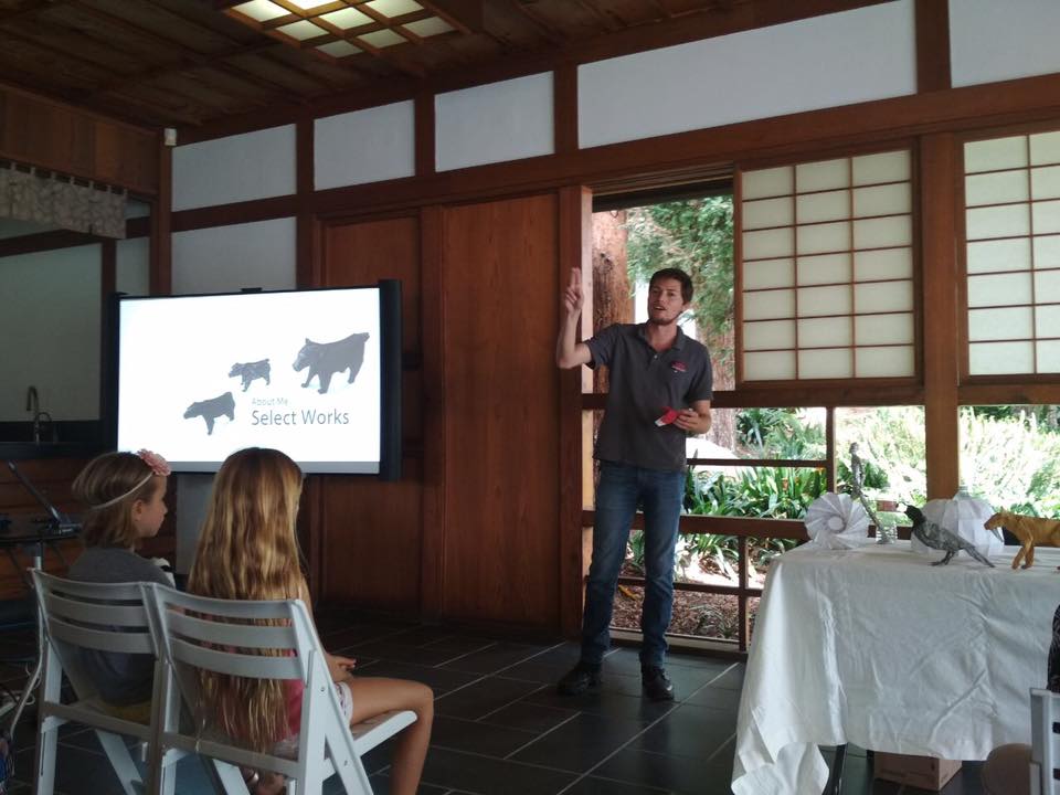
I hope you enjoyed the event as much as we enjoyed having you. Based on the numbers for the day and the many compliments we received about the event, I am going to call the event a success. Numerous people came up to me to share how much they enjoyed themselves and your informative lecture. You demonstrated through your talk and images the role of origami in science, the math involved, and how you can take a passion and turn it into a career. I also want to mention a family member of mine was at your talk and came to me after and commented how fascinating your talk was to her. They mentioned your passion, and your ability to take something complex and make it understandable, as well as exciting.
We truly appreciate you dedicating your time off to engage our visitors and share the relevancy of origami. The Garden strives to offer engaging and memorable events and your participation helps us achieve our goal.

….they all wanted more “Robert time!”
Your presentation at Bring Our Children to Work Day at the Hub was a great hit!
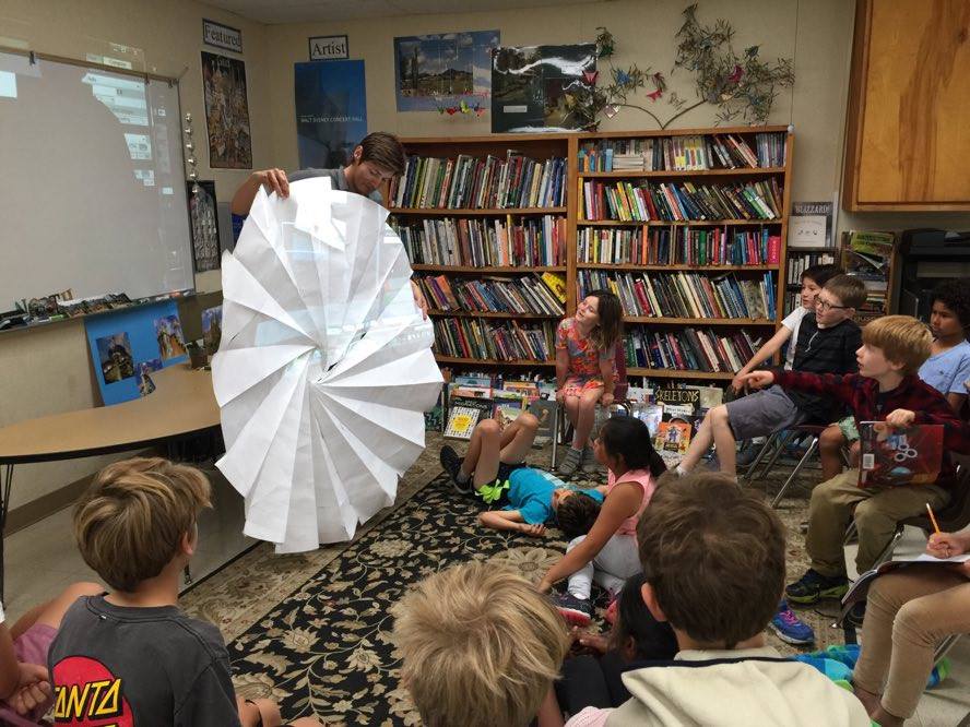
Thank you so much for coming to MCS and sharing your incredible art with us! You have ignited our imaginations with limitless origami possibilities!